Beaglebone: A quick Guide to GPIO Subsystem
Introduction
GPIO subsystem is a very important subsystem that allows the users to interface the board with sensors and other peripherals and allow interaction with real world.Pocket Beagle and Beaglebone black are the two most popular variants among the enthusiasts. Both of which have AM335X at its heat and 2 PRU which operate at 200MHz. On the Pocketbeagle the SIP that you see is by octavo systems, which integrates TI’s AM335X and several other components like LDO, PMIC on a single SIP. IN fact it is this integration which has made the current form factor of pocket beagle possible , further it also leads to faster and quicker development and production time if I would like to prototype on pocketbeagle and then create my own custom board around OSD335X.In this post I will try to declutter the GPIO subsytem. I am using following variant of Linux Linux beaglebone 4.19.94-ti-r42 #1buster SMP PREEMPT Tue Mar 31 19:38:29 UTC 2020 armv7l GNU/Linux
Inside the GPIO Subsystem
In the AM335X there are 4 GPIO modules where each module supports 32 GPIO pins. So in total there are 128 GPIOs . However not all 128 GPIOs are available on the Beaglebone varients. The actual number depends on the variant that you will use.On a beaglebone Black you have 2 Expansion headers P8 and P9 respectively which have 46 pins on each of them. ON P8 one can use 44 GPIO, Pin 1 and 2 are used for ground purposes and on the P9 only 23 pins can be used as GPIO.Similarly on the Pocketbeagle you have P1 and P2 expension headers which have 36 pins each. However 18 pins on P1 and 27 on P2 can be configured in GPIO mode
The figure below shows different columns that you will find in Expension Header section of System Reference Manual. There is a SRM document for each Beaglebone Black and Pocket Beagle.For more details one can go through the SRM LINK

- PIN column is the pin number on the expansion header.
- The PROC column is the pin number on the processor.Further there is a document called Technical Reference Manual (TRM) which can be accessed HERE . On the page no 10 of this document you can see that the SOC is physically divided into 3 section and each pad can be located by combination of column name and row number.
- The Name column tells the default mode of the pin on poweron rest. However you can see the pin configured as in some other mode out of the box that might be due to the fact that a device tree overlay has altered it.
- The MODE columns are the mode setting for each pin. Setting each mode to align with the mode column will give that function on that pin. The mode 7 is the mode in which the pins can behaiave as general purpose input output.
Conversion into Software Friendly naming Convention
In the image above which is taken from SRM, you would have noticed that the GPIOs are represented
using a special convention, for example gpio1[2].This denotes that the pin is the 2nd pin of gpio
module 1. But the
kernel doesnot use this convention. So we need to know the corresponding number for this GPIO that
the kernal would understand.
In order to convert. Use the following algorithum
gpio1[2] = 1* 32 +2 = gpio34
gpio0[4]= 0*32 + 4 = gpio 4
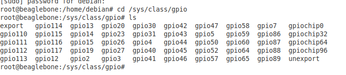
The entry corresponding to each pin can be found in the /sys/class/gpio directory as shown in the
figure below
Mode configuration for GPIO
There is a register that controls the mode configuration settings for each pin. The control module register section in the TRM explains it thoroughly.The PAD/PIN configurtion register starts at address 044E1800H(Base address(0x44E1000H) + 800H). The table below explains the mode configurations.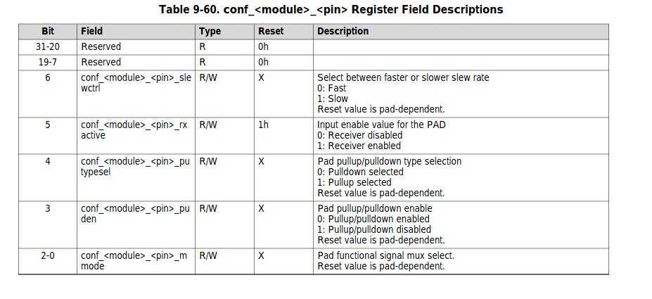
Details of Directory which corresponds to Pad configuration Registers
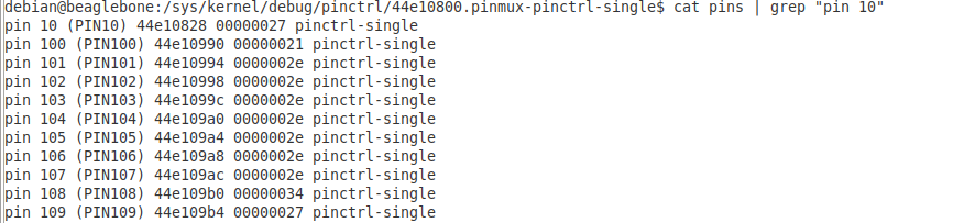
The sys/kernel/debug/pinctrl/44e10800.pinmux-pinctrl-single directory contains information about the configuration of pins as shown in the figure below.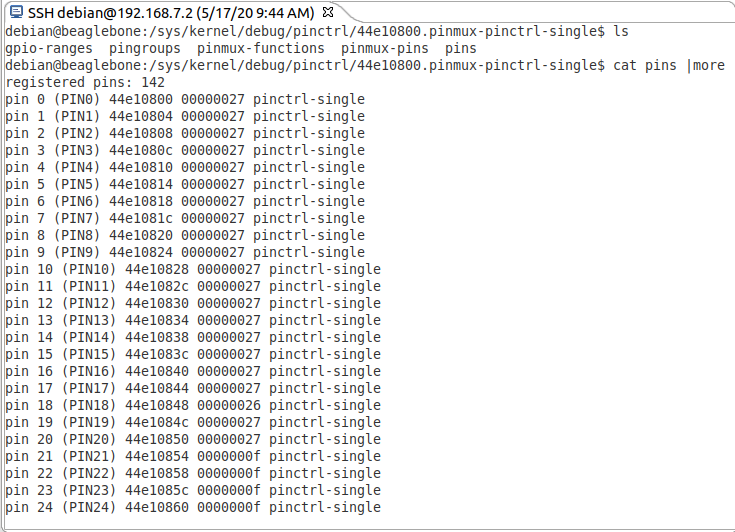
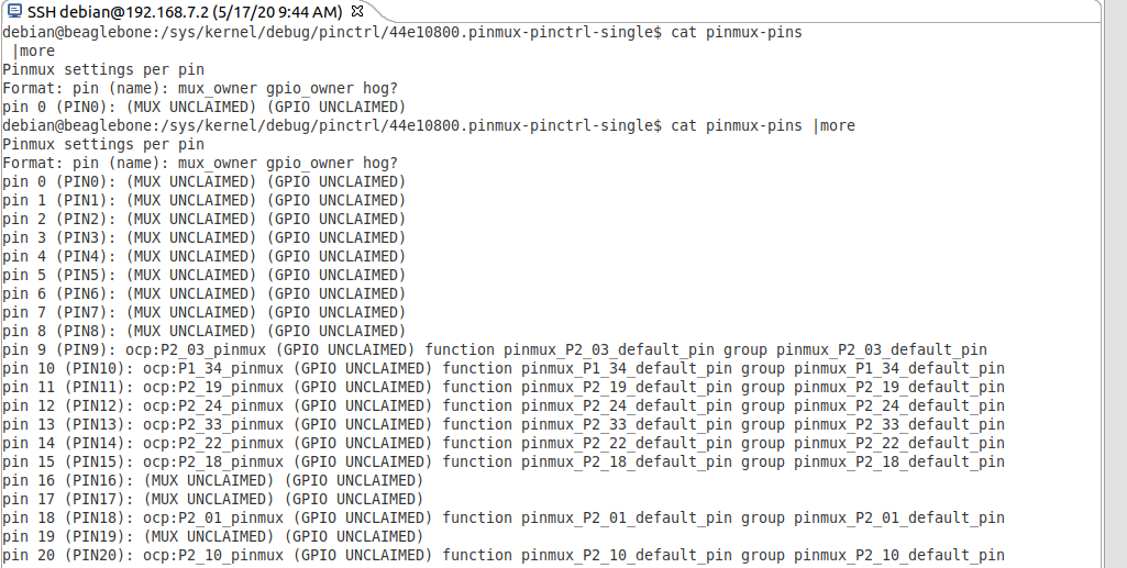
Further You can also see if a pin is already claimed by sub system by running following command as shown in the image inside the syskernel/debug/pinctrl/44e10800.pinmux-pinctrl-single directory.You should be very clearful in dealing with the pins which are already claimed.
Pin Groups
Certain pins can belong to a perticular group, for example the mmc pins can be grouped in a group to
know the groups one can do.
cat pingroups | more
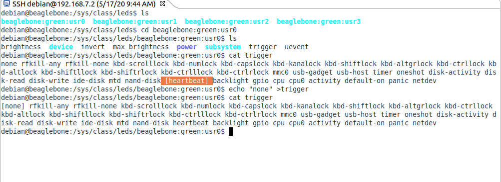
User LEDs and controlling them through sysfs
The SRM tells us that the user LEDs are actually connected as below.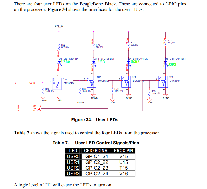
Some Important Links
PocetBeagle SRM LINKBeagleboneBlack SRM LINK
BeagleboneBlack SRM PDF
TRM A335X LINK